![]()
|
|
|
|
ULTRA VIOLET LIGHT DISINFECTION SYSTEMS |
 |
|
|
|
||
|
|
|||
|
|
|||
|
|
UV Disinfection - General |
WATER DISINFECTION USING ULTRAVIOLET TECHNOLOGY Disinfection of water using ultraviolet light (UV) is a proven technology. This safe and effective physical disinfectant is suitable for both large and small applications. Ultraviolet light, better known as UV, is one energy region of the electromagnetic spectrum. In this spectrum UV lies between visible light and X-rays. The shorter the wavelength the greater the energy produced, therefore UV has less en3rgy than the X-ray region and more than visible light. The UV region is made up of four areas, Vacuum UV, UV C, UV B, and UV A. (Figure 1) |
|
|
|
UV Disinfection - Technical Discussion | ||
|
|
UV Inactivation Chart | ||
|
Recommended Installation Residential Recommended Installation Commercial & Industrial Commercial & Industrial UV Systems
|

|
||
|
|
The UV A region (315 - 400 nm) is used
for sun-tanning lamps UV B (260 - 315 nm) and UV C (200 -280 nm) are the
regions that contain the wavelengths most effective for germicidal action.
Figure 1, shows the relationship between the different wavelengths.
Wavelengths most effective in killing microbes lie below 300nm. Those most
effective in producing ozone lie below 200nm. In most cases, we are
interested in killing microbes, not in producing ozone, so we are concerned
primarily with wavelengths between 200 and 300 rum.
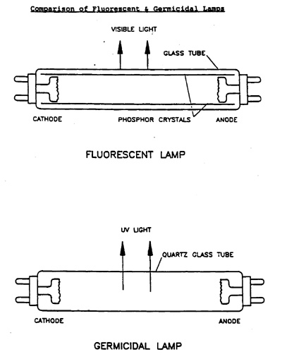
Ultraviolet lamps and fluorescent lamps are similar in design. (Figure 2). UV light is emitted as a result of current flow through the mercury vapor between the electrodes of the lamp. The most commonly used UV lamps (low pressure mercury vapor) produce the majority of their UV output at 253.7nm, a wavelength which is very close to the 260 - 265nm wavelengths which are most effective in killing microbes. The main differences between germicidal and fluorescent lamps are: the germicidal lamp is constructed of UV transmitting quartz; whereas the fluorescent lamp has soft glass with an inside coating of phosphor, which converts UV to visible light. The quartz tube transmits 93% of the lamps UV energy whereas the soft glass emits very little. |
||
|
|||
|
Microorganisms include several
distinct groups of disease causing germs, differing widely in form and life
cycle, but resembling one another in their small size and relatively simple
structure. microorganisms encompass five major groups: Viruses, Bacteria,
Fungi, Algae and Protozoa.
Figure 3 illustrates a basic bacterial cell showing the main structures of interest to us: the cell wall, cytoplasmic membrane, and nucleic acid. The target of UV disinfection is the genetic material, nucleic acid. Microbes are destroyed by UV if the light penetrates through the cell and is absorbed by the nucleic acids. The absorption of UV light by nucleic acids causes a rearrangement of the genetic information, which interferes with the cell's ability to reproduce. A cell that can not reproduce is considered dead; since it is unable to multiply to infectious numbers within a host. |
|||
Figure 3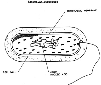
|
|||
| The maximum absorption of UV light by the nucleic acid, DNA, occurs at a wavelength of 260nm. Figure 4 shows the similarity between the ability of UV light to destroy and the ability of this cell's nucleic acid to absorb UV light. The germicidal lamp emitting UV at 254nm is operating very close to the optimized wavelength for maximum absorption by nucleic acids | |||
Figure 4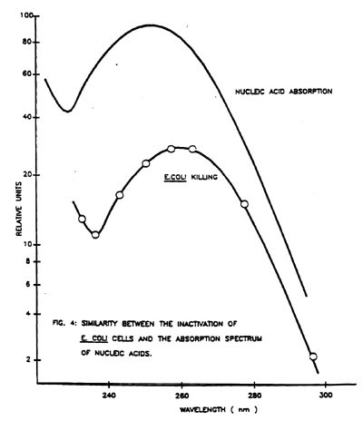
|
|||
|
Microorganisms differ in their
sensitivity to UV light. This variation may be due to cell wall structure,
thickness, and composition; to the presence of UV absorbing proteins; or to
differences in the structure of the nucleic acids themselves. Waterborne
diseases may be caused by a wide variety of pathogenic microorganisms.
Disinfection of drinking water with UV must ensure a maximum dose to cover
this wide variation of UV sensitivities (eg.) 99.9% reduction of E.coli
requires a dose of 7,000 microwatts.sec./sq. cm.; whereas a similar
reduction of protozoa cysts requires a dose of approximately 105,000
microwatts.sec./sq. cm.
UV Dose is a product of intensity multiplied by contact time. Intensity is the amount of UV energy per unit area measured in microwatts per square centimeter. The contact time is the amount of time the solution is exposed to UV in the reactor (measured in seconds). Therefore, UV Dose is expressed in microwatt seconds per square centimeter. Survival curves demonstrate the susceptibility of a specific organism to different doses of UV. |
|||
Figure 5
|
|||
|
Effective UV dosage is reduced by a
loss of UV in passing through water. Transmittance is a measure of the
amount of UV energy, that will pass through 1 centimeter of water. This is
measured using a UV spectrophotometer. The National Sanitation Foundation
(NSF) UV Disinfection Committee has suggested that drinking water should
have a UV transmittance greater than 75% at a wavelength of 254nm.
Appropriate water treatment devices can be used to reach the required level
of transmittance.
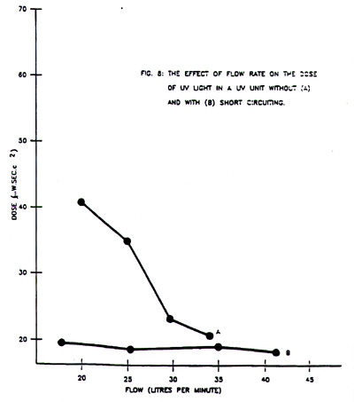
Water quality influences the effectiveness of all types of disinfection, including UV. The three major concerns affecting UV performance are; suspended solids, absorption of UV, and coating on the quartz sleeves. All reduce the intensity of UV energy reaching the microbes. Suspended solids create shadows that prevent UV energy from reaching microbes. This can be overcome by designing the reactor to create turbulent flow patterns bringing microbes out of shadowed positions, but microbes within particles can not be reached without adequate intensity to penetrate the particles. Absorption of UV light by various soluble molecules reduces the amount of UV energy available to penetrate through the water layer to reach the nucleic acids. Humic acids, tannins and iron, commonly found in drinking water are examples of UV absorbing compounds. Calcium and magnesium (hardness), manganese and iron at levels that meet current potable water standards will not effect the UV disinfection process, but over a period of time these elements may precipitate on the lamp sleeve and reduce the intensity which enters the water layer. These conditions can and should be pretreated using proven technologies. UV manufacturers produce systems ranging in size from 0.5 GP)( to several hundred GPM. The key elements of all UV systems are the ballast and lamp combination, a Teflon or quartz sleeve to protect the lamp, and a properly designed reactor chamber. For maximum efficiency, the UV lamp must be driven properly to ensure optimal germicidal output. The ballast is the controlling device that drives the lamp at the desired electrical conditions. The germicidal output of UV lamps gradually decreases over a period of use, and most manufacturers claim that their systems have an effective life ranging between 6,000 and 12,000 hours. For optimal UV output the lamp operates at 400C or 1040F. The sleeve separates the lamp from the water, to provide electrical safety and to maintain lamp operating temperature; so that the UV output does not fluctuate with water temperature. The hydraulics of the reactor determine the contact time. Therefore, UV output is affected by flow rates, flow patterns in the reactor (short circuiting), shadowing in the reactor, and lamp configuration in multiple lamp systems. When designing UV Systems the theoretical calculated contact time, and the actual contact time can vary greatly. This variation will influence the actual UV dose compared with the calculated dose (Dose = Intensity x Time) by decreasing the value of time. (Figure 8) The actual UV dose may be determined with a bioassay. |
|||
|
|||
|
Bioassays may be performed to
determine the UV dose at a given flow rate. This technique involves the
preparation of a standard survival curve over a wide range of doses for a
specific test organism. The standard curve is prepared by exposing a pure
suspension of a known number of organisms to a measured intensity of UV for
a measured time, using a collimated beam apparatus. The ratio of survivors
to initial numbers can then be plotted against dose.
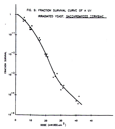
Figure 9 shows the survival curve for Saccharomyces cervisiae, a yeast. The survival curve demonstrates the susceptibility of that specific organism to UV dose. The same organism is then used to spike the test water before entering the test UV unit. Samples are taken before and after passing through the UV unit at a range of measured flow rates. The ratio of survivors to initial numbers can then be compared to the standard curve and the dose may be determined for each flow rate. |
|||
|
|||
|
The distribution system should be
checked for places where microbial contamination could collect. These dead
spots should be eliminated from the distribution system. Shocking with a
bleach should kill any microbes remaining in the plumbing system.
UV disinfection standards are still based on the 1966 statement by the U.S. Department .cf Health, Education and Welfare, that UV disinfection equipment required a UV dose of 16,000 mW.sec./sq. cm. Most UV manufacturers claim that their units produce a UV dose ranging from 16,000 to 30,000 mW.sec./sq. cm. at various transmittances. The UV performance of a unit can be determined by the bioassay technique. The UV manufacturers, National Sanitation Foundation and the governments of Canada and the United States of America, have been trying to set a standard for UV disinfection for years. This standard is for both contaminated and potable water.
For contaminated water, the system must product a UV dose of 38,000 mW.sec./sq. cm. at the failsafe point. It will therefore require a sensor to measure the UV intensity.
For potable water, the system must produce a UV dose of 16,000 mW.sec./sq. cm. at 50% of the UV lamp's normal output. The most common UV applications fall into the following categories, POU, POE and industrial. When installing a POU system, it is usually installed on the cold water line and the disinfected water should be dispensed from a separate faucet to ensure that the water does not become decontaminated by using the same faucet that is used for untreated water. POE equipment for home applications is installed prior to the line split for hot and cold water. Most large industrial applications are usually site specific, depending on their application, what microbes they are concerned with, the water quality, and effluent discharge. In most UV applications, following a few simple rules will eliminate most UV problems. When you install a UV system ensure that you leave enough clearance so that lamp replacement and any maintenance the system requires can be done without having to remove the system. The simplest way to size a unit is to determine the capacity that the distribution system will provide and install a system that will disinfect that volume (gallons/minutes). By following this procedure, there will be minimum effect on any pressure loss. If flow capacity varies greatly, it is best to install a flow controlling device to restrict the volume to the designed capacity of the disinfection system. If the volume to be disinfected exceeds the capacity of the UV system, the loss of contact time will reduce UV dose. Since UV is a physical process, (nothing is added to the water) it does not leave a residual disinfectant in the distribution system. The distribution system should be disinfected (shocked) when a UV unit is installed. All other pretreatment devices should be installed ahead of the UV system. There may be a few applications where this doesn't apply (such as sub-micron filtration at point of use). Microbial testing is the only direct way to verify that a UV system is providing proper disinfection; however, safety features to monitor UV intensity are available to ensure that adequate disinfection conditions are present. The UV detectors will activate audio and visual lamp alarms and activate solenoids1 which Stop water flow. If the UV detector is not monitoring germicidal UV below 300nm (only longer wavelengths)1 it will be unable to accurately monitor loss of UV output and the effect of UV absorbing compounds in the water. To determine if the UV detector is actually monitoring germicidal wavelengths, place two pieces of film transparency between the UV lamp and the detection device, if the system goes into failsafe (alarm), the detector is reading wavelengths less than 300nm, which is the germicidal region. Film transparency starts to transmit light at wavelengths greater than 300nm. Other features available to enhance UV system performance, maintenance and testing included: flow controllers, solenoid valves, sample ports, cleaning mechanisms, thermistors, and running time meters. UV is normally installed in situations where the potable water is contaminated. However, many studies have proven that other treatment devices; such as softeners and carbon filters, support the growth of microorganisms, and even though these microbes may not be pathogenic, they substantially increase the heterotrophic counts well above the recommended level of 500 per milliliter. The February 1, 1990 Quick View published by the water Quality Association stated that in France a law has been proposed that would ban water softening of cold water pipes due to microbial growth in resin beds. In Italy, the law bans carbon filters on all drinking water supplies and requires disinfection of the resin bed with each regeneration. In conclusion, UV disinfection is a physical process that is both an effective and natural way to destroy microorganisms. The advantages of UV disinfection include:
|
|||